When assessing a patent for its Standard Essential Patent (SEP) potential, the real challenge often lies not in whether the technology is relevant but in proving it, rigorously and clause by clause, against a living standard document. Most patents appear to map cleanly at first glance. The difficulty emerges when claim language carries abstract mathematical constructs, frequency-domain descriptions, and signal-processing logic that must be traced to specific normative text in the standard.
A recent Wi-Fi SEP evaluation project focused on US 12XXXX75, a patent covering a method for a wake-up receiver (WUR). It began with a deceptively simple question from the client:
“Does this patent read on the IEEE 802.11-2024 standard and can it be monetized?”
On the surface, the patent’s claims described a method for receiving a wake-up signal (WUS) over a frequency range, filtering it through a channel-selective filter, and modulating the signal on two or more equidistantly spaced carrier frequencies. These are real and specific engineering choices. But the challenge was proving, mathematically and normatively, that every element of the independent claim found its exact counterpart in the IEEE 802.11-2024 standard including one particularly intricate geometric relationship buried in the final claim limitation.
The preliminary read of the patent was encouraging. The independent claim describes a method for a WUR that:
Receives a wake-up signal (WUS) over a frequency range with a signal bandwidth
Filters the received WUS through a filter with a defined filter bandwidth
Modulates the digital WUS sequence on two or more equidistantly spaced carrier frequencies
Requires that the lowest and highest carrier frequencies are each separated from the respective edge of the frequency range by half the carrier frequency interval
The IEEE 802.11-2024 standard’s Section 30 Wake-Up Radio (WUR) PHY specification defines precisely this type of receiver-side operation. The WUR PHY uses multicarrier on-off keying (MC-OOK) to transmit and receive WUR signals within a 20 MHz operating channel, using a specific set of equidistant subcarriers. The alignment was strong but incomplete without resolving the final limitation.
The limitation is where the mapping became technically demanding. The claim requires that:
“…a lowest one of the carrier frequencies and a highest one of the carrier frequencies of the … from a respective edge of the frequency range.”
This is not a qualitative description. It is a quantitative geometric claim about the placement of the outermost active subcarriers relative to the edges of the transmission channel. Proving it required going beyond the normative text and solving the underlying signal-processing mathematics directly from the standard’s parameters.
Working Through the Mathematics
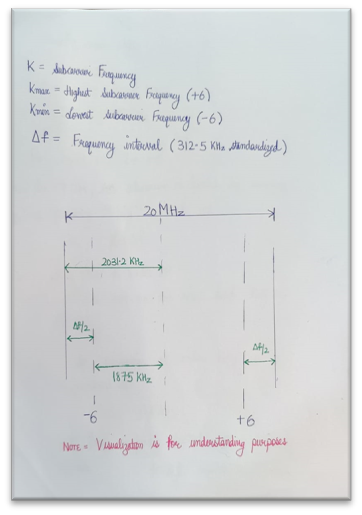
The IEEE 802.11-2024 standard defines the following parameters for MC-OOK transmission:
Active subcarrier indices: k = (−6, −4, −2, 2, 4, 6)
Subcarrier spacing: Δf = 312.5 kHz
IDFT size: 64-point, sampled at 20 MHz
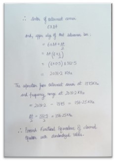
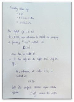
The outermost active subcarriers sit at k = ±6. Their frequency offsets from the channel center are:
f_outer = ±6 × 312.5 kHz = ±1875 kHz
Now, where is the “edge of the frequency range”? In OFDM-based systems, the edge of the frequency range defined by the subcarrier grid is conventionally placed at half a subcarrier spacing beyond the outermost subcarrier that is, at (k_max + 0.5) × Δf:
And half the carrier frequency interval (Δf/2) is:
312.5 kHz / 2 = 156.25 kHz
The two values are identical. The lowest and highest active carrier frequencies are each separated from the respective edge of the 20 MHz frequency range by exactly half the subcarrier spacing of 312.5 kHz, confirming the claimed relationship.
This was the breakthrough. The claim’s final limitation, which appeared abstract, is in fact a direct mathematical consequence of the MC-OOK subcarrier placement defined in IEEE 802.11-2024 Clause 30.
With the SEP status established including the resolution of the challenging final limitation the analysis unlocked several downstream opportunities for the patent owner:
Licensing leverage. The confirmed mapping to IEEE 802.11-2024 provides a concrete, defensible basis for licensing discussions with device manufacturers implementing Wi-Fi 6/6E WUR functionality. Any chipset or device that supports the WUR PHY as defined in 802.11-2024 Clause 30 is a potential licensing target.
Portfolio positioning. Wi-Fi 6 and Wi-Fi 6E deployments have accelerated significantly across consumer electronics, IoT devices, enterprise networking, and automotive applications. WUR, specifically, addresses the low-power connectivity use case central to battery-powered IoT. A confirmed SEP in this space carries real commercial weight.
Prosecution and portfolio strategy. The mathematical derivation work produced during the mapping exercise particularly the subcarrier edge-separation proof can inform continuation filings or claim amendments that more explicitly recite the standard-compliant parameters, potentially strengthening the patent family’s licensing position further.
The Wi-Fi 6 WUR mapping project is a good illustration of what rigorous SEP analysis looks like when the standard doesn’t hand you the answer directly. The technology was clearly aligned. The standard was clearly relevant. But the final link a specific, quantitative geometric relationship between subcarrier placement and channel edges required working through the mathematics of the OFDM subcarrier grid from first principles.
That is the work. And it is the work that determines whether a patent remains a theoretical asset or becomes an actionable one.
In the quest for cleaner transportation and reduced greenhouse gas emissions, hydrogen fuel cell vehicles (FCVs) are emerging as a promising solution. These vehicles harness the power of hydrogen, a lightweight, abundant element, to generate electricity on board, producing only water and heat as byproducts. While still in the early stages of mass adoption compared to battery electric vehicles (BEVs), FCVs offer unique advantages that could make them a major player in the sustainable mobility ecosystem.
How Hydrogen Fuel Cell Vehicles Work
Hydrogen fuel cell vehicles operate using a technology known as a proton exchange membrane (PEM) fuel cell. Here’s a simplified breakdown of how it works:
Hydrogen Storage: Hydrogen gas is stored in high-pressure tanks onboard the vehicle.
Fuel Cell Stack: Hydrogen enters the fuel cell stack, where it is split into protons and electrons.
Electricity Generation: The electrons are routed through an external circuit (creating an electric current to power the motor), while protons pass through the membrane.
Combining with Oxygen: The electrons and protons recombine with oxygen (from the air) at the cathode, forming water vapor—released through the tailpipe.
Unlike internal combustion engines, FCVs produce zero tailpipe emissions other than water vapor, and unlike battery EVs, they can be refueled in minutes.
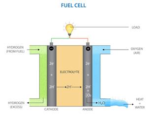
A proton exchange membrane (PEM) fuel cell, also referred to as a polymer electrolyte membrane fuel cell, produces electricity by undergoing a chemical reaction between hydrogen and oxygen. Here’s a comprehensive description of the process:
The fundamental elements of a PEM fuel cell consist of the anode, cathode, electrolyte, and catalyst. The anode is the electrode where hydrogen gas is introduced. The cathode is the electrode that receives oxygen gas for the electrolysis process. The electrolyte is a membrane that permits the passage of protons but restricts the movement of electrons. The catalyst, typically platinum, is employed to accelerate the reaction at the electrodes.
The process starts with the splitting of hydrogen at the anode. Hydrogen gas is provided to the anode, where, with the assistance of a platinum catalyst, hydrogen molecules are broken down into protons and electrons. The proton-conducting membrane, also known as the electrolyte, enables the movement of protons towards the cathode while preventing the passage of electrons. Because the electrons cannot pass through the electrolyte, they move through an external circuit, generating an electric current that can be utilized to perform tasks like operating an electric motor. Oxygen gas is provided to the cathode. In this scenario, oxygen molecules interact with the protons passing through the electrolyte and the electrons flowing through the external circuit to produce water. The complete chemical reaction in a PEM fuel cell generates water, electricity, and heat. PEM fuel cells offer a clean and efficient energy solution, serving as a sustainable alternative to conventional fossil fuel-based energy systems.
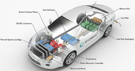
Key Components of a Hydrogen Fuel Cell Electric Car
Battery (auxiliary): In an electric drive vehicle, the low-voltage auxiliary battery provides electricity to start the car before the traction battery is engaged; it also powers vehicle accessories.
Battery pack: This high-voltage battery stores energy generated from regenerative braking and provides supplemental power to the electric traction motor.
DC/DC converter: This device converts higher-voltage DC power from the traction battery pack to the lower-voltage DC power needed to run vehicle accessories and recharge the auxiliary battery.
Electric traction motor (FCEV): Using power from the fuel cell and the traction battery pack, this motor drives the vehicle’s wheels. Some vehicles use motor generators that perform both the drive and regeneration functions.
Fuel cell stack: An assembly of individual membrane electrodes that use hydrogen and oxygen to produce electricity.
Fuel filler: A nozzle from a fuel dispenser attaches to the receptacle on the vehicle to fill the tank.
Fuel tank (hydrogen): Stores hydrogen gas onboard the vehicle until it’s needed by the fuel cell.
Power electronics controller (FCEV): This unit manages the flow of electrical energy delivered by the fuel cell and the traction battery, controlling the speed of the electric traction motor and the torque it produces.
Thermal system (cooling) – (FCEV): This system maintains a proper operating temperature range of the fuel cell, electric motor, power electronics, and other components.
Transmission (electric): The transmission transfers mechanical power from the electric traction motor to drive the wheels.
Advantages of Hydrogen Fuel Cell Vehicles
Hydrogen FCVs provide several benefits, especially for long-range and heavy-duty applications:
1. Fast Refueling
FCVs can be refueled in 3–5 minutes, similar to gasoline vehicles, which is a significant advantage over battery EVs that often require longer charging times.
2. Long Driving Range
Hydrogen vehicles can travel 300–400+ miles on a single tank, making them suitable for long-distance driving and logistics.
3. Zero Emissions
Hydrogen fuel cells emit only water vapor, offering a clean alternative to fossil fuels and helping reduce urban air pollution.
4. Reduced Battery Dependency
FCVs use smaller batteries, reducing dependence on lithium and other rare earth metals, often associated with mining and geopolitical concerns.
5. High Efficiency
Fuel cell systems are more efficient than internal combustion engines, especially in stop-and-go traffic.
Challenges Facing Hydrogen FCVs
Despite the advantages, hydrogen vehicles face several significant hurdles:
1. Lack of Infrastructure
Hydrogen refueling stations are scarce and expensive to build, limiting the practicality of FCVs outside select regions (e.g., California, Japan, South Korea).
2. High Costs
Fuel cell systems and hydrogen storage tanks are still costly, though prices are falling with advances in manufacturing and scale.
3. Hydrogen Production
Most hydrogen today is produced via steam methane reforming, which emits CO₂. For FCVs to be truly green, hydrogen must come from renewable sources like electrolysis powered by wind or solar.
4. Public Awareness and Acceptance
Compared to battery EVs, FCVs suffer from lower public familiarity, slowing adoption and investment.
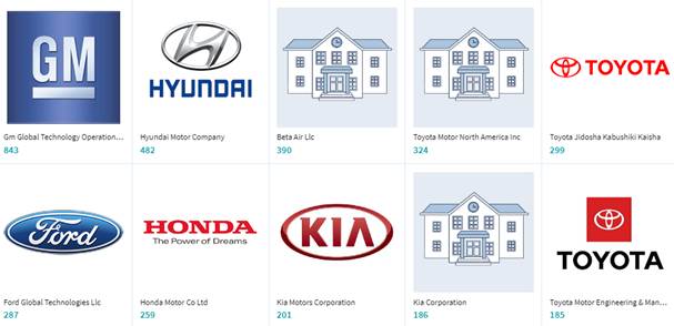
Key Market Players in Hydrogen FCVs
Several automotive and energy companies are investing in hydrogen fuel cell technology, recognizing its potential in both passenger and commercial vehicle sectors.
1. Toyota
Toyota is a pioneer in hydrogen mobility. Its flagship FCV, the Toyota Mirai, was among the first commercially available hydrogen cars. Now in its second generation, the Mirai offers over 400 miles of range and serves as a benchmark for the industry. Toyota is also investing in hydrogen-powered trucks in partnership with Hino Motors and exploring fuel cell buses.
2. Hyundai
Hyundai introduced the NEXO, a hydrogen-powered SUV with a sleek design and a range of around 380 miles. The company is also pushing hydrogen solutions in commercial transport, notably with its XCIENT Fuel Cell trucks already operating in Switzerland and other markets.
3. Honda
Honda partnered with GM to develop fuel cell technologies and released the Clarity Fuel Cell, though it has paused production temporarily. Honda remains committed to fuel cells, especially for future applications in larger vehicles and infrastructure.
4. Nikola Motors
Nikola focuses on hydrogen-powered heavy-duty trucks. While it has faced some controversies and leadership changes, the company continues developing hydrogen fuel cell Class 8 trucks and building fueling infrastructure.
5. Ballard Power Systems
Based in Canada, Ballard is a leading developer of PEM fuel cells. Rather than producing vehicles, it supplies fuel cell technology to automakers and industrial partners worldwide, including buses, trucks, trains, and marine vessels.
6. Plug Power
Plug Power is focused on the hydrogen ecosystem—producing, distributing, and using green hydrogen. It powers a large fleet of hydrogen forklifts and is expanding into transportation and stationary power systems.
7. Daimler Truck and Volvo Group
Through a joint venture called Cellcentric, these two heavyweights are co-developing hydrogen fuel cell systems for trucks, aiming for commercialization later this decade. Their efforts reflect growing interest in hydrogen for long-haul trucking, where batteries may fall short.
Hyundai has revealed its updated Nexo hydrogen SUV. The latest model, which was initially showcased as the concept car at the October event, completely revamps its appearance and incorporates numerous enhancements, such as increased power, extended range, and the unexpected capability to tow. The updated nexo has undergone a significant mechanical upgrade, resulting in an increase in output from the electric motor to 150 kilowatts (approximately 201 horsepower), compared to the previous 120 kilowatts. Torque remains consistent at 350 nm, but Hyundai asserts a faster 0-100 km/h (0-62 mph) acceleration time of 7.8 seconds, a decrease from 9.2 seconds. More relevant for most buyers is the extra range: now targeting over 700 km (435 miles) on the Korean test cycle, thanks to a larger 6.69 kg hydrogen tank (up from 6.33 kg), improved energy density, and better aerodynamic efficiency. The fuel cell stack itself now delivers 110 kw of gross power and benefits from low-temperature improvements, better durability, and something Hyundai calls a ‘wake up’ anti-freezing function – suggesting the system is now better suited to colder climates and real-world winter starts. Additionally, there is a new high-voltage battery with double the power output (80 kw vs. 40 kw), which aids in both performance and energy buffering, particularly during rapid throttle changes or regeneration. European models will also provide towing capacity – up to 1,000 kg. Which is the first time a hydrogen car has officially provided a tow rating, transforming nexo from a mere science experiment with seats into a proper SUV that can perform essential tasks.
Toyota’s hydrogen-powered mirai saloon returns for the 2025 model year with a simplified lineup, some newly standard features, and the same quiet commitment to showing how a fuel cell car should be done. Toyota has included a few previously optional features in the standard lineup for the my25 xle. New standard kit includes a panoramic view monitor (with overhead 360-degree imagery), front and rear parking assist with automatic braking, dual-tone heated mirrors, front footwell illumination, and digital key smartphone access – although the latter requires an active remote connect subscription (obviously, this is 2025) and, naturally, a functioning 4g signal. The car model remains unchanged. It’s still built on Toyota’s GA-L platform – the same one used under the Lexus ls – and retains a rear-wheel-drive layout, with an electric motor mounted at the back delivering smooth, unflustered acceleration. Hydrogen is stored in two high-pressure tanks tucked beneath the rear seats and boot floor, and combined with outside air in a fuel cell stack under the bonnet.
Artificial intelligence (AI) and machine learning (ML) have evolved into game-changing technologies with limitless applications ranging from natural language processing to the automobile sector. These applications need a significant amount of computing power, and memory is an often neglected resource. Fast memory is crucial for AI and ML activities, and GDDR6 memory has established itself as a prominent participant in this industry where high speed and computing power are necessary. The following article will investigate the usage of GDDR6 in AI and ML applications, as well as current IP trends in this crucial subject.
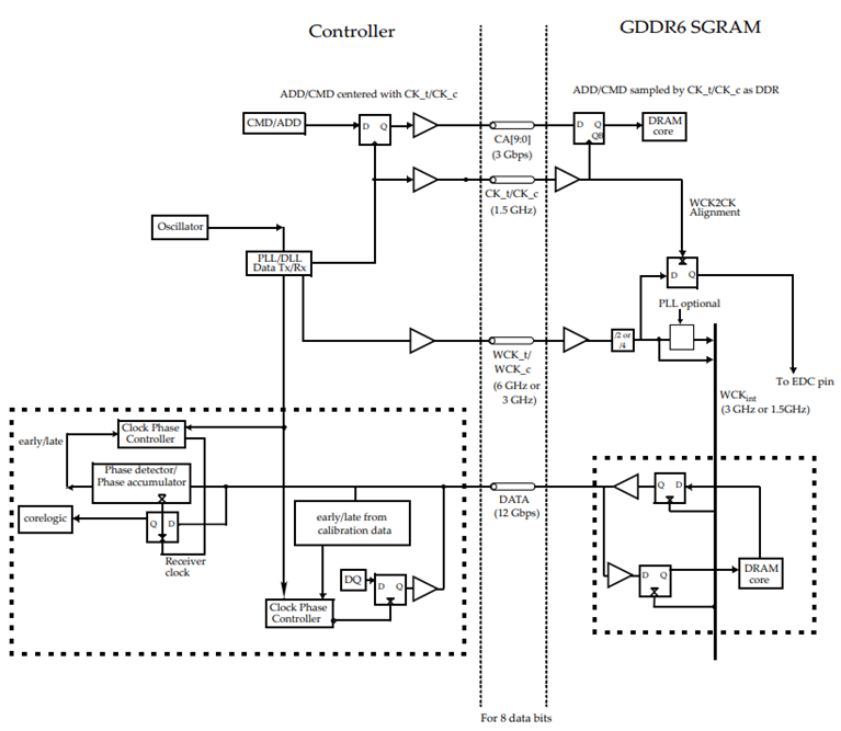
Architecture of GDDR6
High-speed dynamic random-access memory with high bandwidth requirements is the GDDR6 DRAM. The high-speed interface of the GDDR6 SGRAM is designed for point-to-point communications to a host controller. To accomplish high-speed operation, GDDR6 employs a 16n prefetch architecture and a DDR or QDR interface. The architecture of the technology has two 16-bit wide, completely independent channels.
For AI and ML processes, including the training and inference phases, large-scale data processing is necessary. Avoid AI GPUs (Graphics Processing Units) have evolved into the workhorses of AI and ML systems to make sense of this data. The parallel processing capabilities of GPUs are outstanding, which is crucial for addressing the computational demands of workloads for AI and ML.
Data is a crucial piece of information, high-speed memory is needed to store and retrieve massive volumes of data, and GPU performance depends on data analysis. Since the GDDR5 and GDDR5X chips from earlier generations couldn’t handle data transmission speeds more than 12 Gbps/pin, these applications demand faster memory. Here, GDDR6 memory plays a crucial function. AI and ML performance gains require memory to be maintained, hence High Bandwidth Memory (HBM) and GDDR6 offer best-in-class performance in this situation. The Rambus GDDR6 memory subsystem is designed for performance and power efficiency and was created to meet the high-bandwidth, low-latency requirements of AI and ML. The demand for HBM DRAM has significantly increased for gaming consoles and graphics cards as a result of recent developments in artificial intelligence, virtual reality, deep learning, self-driving cars, etc.
Micron’s GDDR6 Memory
Micron’s industry-leading technology enables the next generation faster, smarter global infrastructures, facilitating artificial intelligence (AI), machine learning, and generative AI for gaming. Micron has launched GDDR6X with NVIDIA GeForce® RTX™ 3090 and GeForce® RTX™ 3080 GPUs due to its high-performance computing, higher frame rates, and increased memory bandwidth.
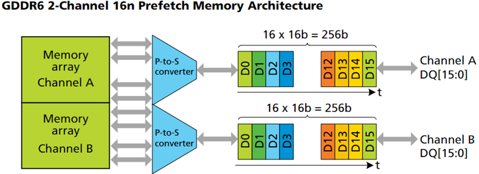
Micron GDDR6 SGRAMs were designed to work with a 1.35V power supply, making them ideal for graphics cards. The memory controller receives a 32-bit wide data interface from GDDR6 devices. GDDR6 employs two channels that are completely independent of one another. A write or read memory access is 256 bits or 32 bytes wide for each channel. Each 256-bit data packet is converted by a parallel-to-serial converter into 16×16-bit data words that are consecutively broadcast via the 16-bit data bus. Originally designed for graphics processing, GDDR6 is a high-performance memory solution that delivers faster data packet processing. GDDR6 supports an IEEE1149.1-2013 compliant boundary scan. Boundary scan allows testing of interconnect on the PCB during manufacturing using state-of-the-art automatic test pattern generation (ATPG) tools.
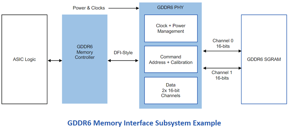
The JEDEC GDDR6 JESD250C standard is fully supported by the Rambus GDDR6 interface. The Rambus GDDR6 memory interface subsystem fulfills the high-bandwidth, low-latency needs of AI/ML inference and is built for performance and power economy. It includes a PHY and a digital controller that gives users a full GDDR6 memory subsystem. It provides an industry-leading 24 Gb/s per pin and enables two channels with a combined data width of 32 bits. Each channel supports 16 bits. The Rambus GDDR6 interface has a bandwidth of 96GB/s at 24 Gb/s per pin.
A large variety of AI/ML applications from many industries employ GDDR6 memory. Here are some actual instances of AI/ML applications that make use of GDDR6 memory:
FPGA-based AI applications
Micron in their recent new release focused on the development of High-Performance FPGAs based GDDR6 memory for AI applications built on TSMC 7nm process technology with FPGA from Achronix.
2. GDDR6 memory is ideal for AI/ML inference at the edge where fast storage is essential. It offers better memory bandwidth, system speed, and low latency performance, which makes the system to be used for real-time computing of large amounts of data.
3. Advanced driver assistance systems (ADAS)
ADAS employs GDDR6 memory in visual recognition for processing large amounts of visual data, in multiple sensors for tracking and detection, and for real-time decision-making where a large amount of neutral network-based data is analyzed to reduce accidents and for passenger safety.
4. Cloud Gaming
To provide a smooth gaming experience, cloud gaming uses GDDR6 memory, which is fast memory.
5. Healthcare and Medicine:
GDDR6 is used in faster analysis of medical data in the medical industry implemented with AI algorithms for diagnosis and treatment.
IP Trends in GDDR6 use in machine learning and Artificial intelligence
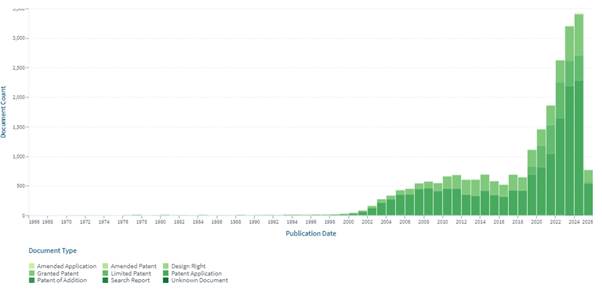
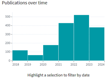
As the importance of high-speed with low latency memory is increasing, there is a significant growth in the patent filing trends witnessed across the globe. The Highest number of patents granted was in 2022 with 212 patents and the highest number of patent applications filed was ~408 in 2022.
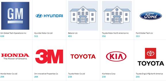
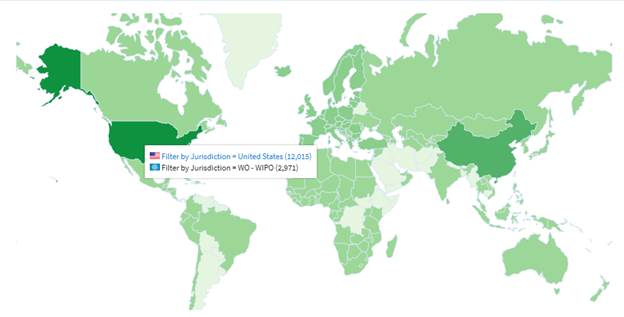
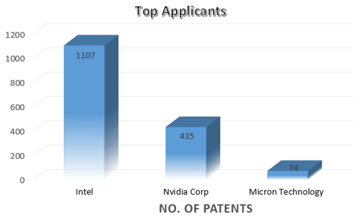
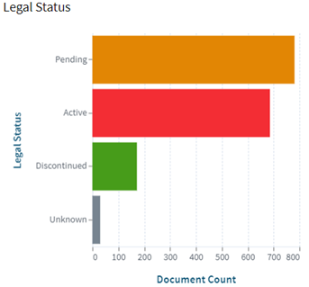
INTEL is a dominant player in the market with ~1107 patent families. So far, it has 2.5 times more patent families than NVIDIA Corp., which comes second with 435 patent families. Micron Technology is the third-largest patent holder in the domain.
Other key players in the domain are SK Hynix, Samsung, and AMD.
High-speed memory is a hero who goes unnoticed in the quick-paced world of AI and ML, where every millisecond matters. It has stepped up to the plate, providing great bandwidth, low latency, and enormous capacity, making GDDR6 memory an essential part of AI and ML systems. The IP trends for GDDR6 technology indicate continued attempts to enhance memory solutions for these cutting-edge technologies as demand for AI and ML capabilities rises. These developments bode well for future AI and ML developments, which should become much more amazing.
We use cookies to ensure that we give you the best experience on our website. If you continue to use this site we will assume that you are happy with it.